Skip to content
With the development of switching power supplies, soft switching technology has been widely developed and applied, and many high-efficiency circuit topologies have been studied, mainly PFM-type soft switching topologies and PWM-type soft switching topologies.
In recent years, with the widespread application of third-generation semiconductor devices GAN and the continuous development of PD power supplies, this has provided another opportunity for the development of power converters. For half-bridge converters, if properly designed, soft
switching conversion can be achieved, so that the switching power supply has higher efficiency and greatly reduces the size of the power supply.
1 Working principles of two converters
1.1 Half-bridge flyback converter
Figures 1 and 2 show the circuit diagram and working waveform of the half-bridge flyback converter respectively.
Figure 1 includes two complementary controlled power MOSFETs (S1 and S2), where the duty cycle of S1 is D and the duty cycle of S2 is (1-D); a DC blocking capacitor Cr, the voltage on which is used as the power supply when S2 is turned on; a center-tapped transformer Tr, the number of turns of the primary side is Np, and the number of turns of the secondary side is Ns; an output rectifier diode D1; an output filter capacitor Cout; and output rectifier tube peak absorption resistors and capacitors R1 and C1.
As can be seen from the schematic diagram, the primary part of the half-bridge flyback converter is the same as the traditional asymmetric half-bridge (AHB) converter, and the secondary part is the same as the flyback converter. The steady-state working principle of the half-bridge flyback converter is as follows.
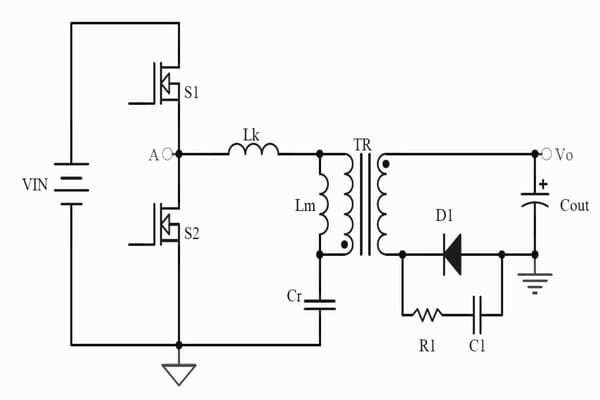
Figure 1: Half-bridge flyback converter
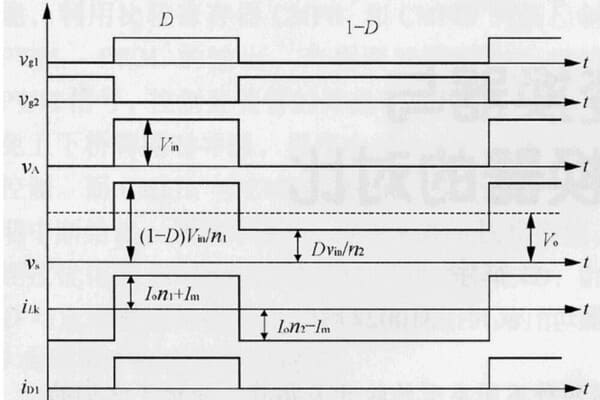
Figure 2 Working principle of half-bridge flyback converter
1) When S1 is turned on and S2 is turned off, the primary side of the transformer is subjected to a forward voltage, and the secondary side Ns does not work; the diode D1 is cut off; the transformer stores energy;
2) When S2 is turned on and S1 is turned off, the voltage on the DC blocking capacitor Cr is applied to the primary side of the transformer, the secondary side Ns2 works, and the diode D1 is turned on.
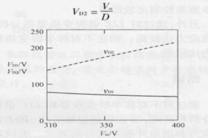
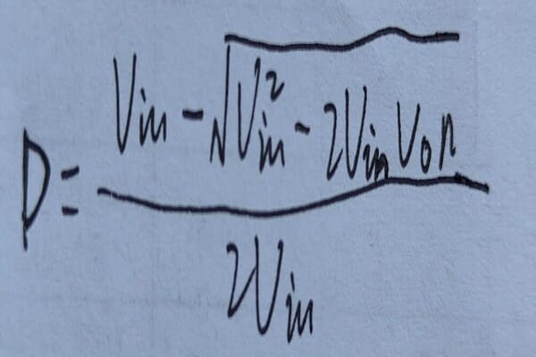
In Figure 2, n1=Np/Ns, and n1=n. By analyzing the circuit, the calculation formula for the duty cycle D of the half-bridge flyback converter can be obtained:
1.2 Half-bridge resonant converter
The half-bridge resonant converter is what is commonly referred to as the LLC resonant converter. Figures 3 and 4 show the circuit diagram and
operating waveform of the half-bridge resonant converter respectively.
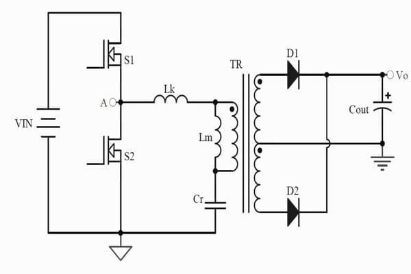
Figure 3: Half-bridge resonant converter
In Figure 3, there are two power MOSFETs (S1 and S2), both of which have a duty cycle of 0.5; a resonant capacitor Cr, a center-tapped transformer Tr with equal turns on the secondary side, a leakage inductance Lk of Tr, and an exciting inductance Lm. Lm is also a resonant inductor in a certain period of time. Therefore, the resonant elements in the half-bridge resonant converter are mainly composed of the above three resonant elements, namely, the resonant capacitor Cr, the inductor Lk and the exciting inductor Lm; the half-bridge full-wave rectifier diodes D1 and D2, and the output capacitor Cout.
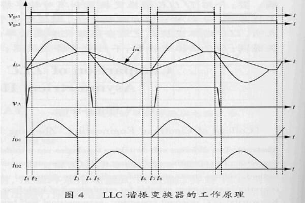
Figure 4: Working principle of half-bridge resonant converter
Figure 2: The steady-state working principle of the LLC converter is as follows.
1) [t1, t2] When t=t1, S2 is turned off, and the resonant current discharges the parasitic capacitance of S1 until the voltage on S1 is zero, and then the body diode of S1 is turned on. In this stage, D1 is turned on, and the voltage on Lm is clamped by the output voltage. Therefore, only Lk and Cr participate in the resonance.
2) [t2, t3] When t=t2, S1 is turned on under zero voltage conditions, and the primary side of the transformer is subjected to a forward voltage; D1 continues to be turned on, and S2 and D2 are turned off. At this time, Cr and Lk participate in the resonance, while Lm does not participate in the resonance.
3) [t3, t4] When t=t3, S1 is still turned on, while D1 and D2 are in the off state, and the secondary side of Tr is disconnected from the circuit. At this time, Lm, Lk and Cr participate in the resonance together. In the actual circuit, Lm is much larger than Lk. Therefore, it can be considered that the excitation current and the resonant current remain unchanged at this stage.
4)〔t4, t5〕When t=t4, S1 is turned off, and the resonant current discharges the parasitic capacitance of S2 until the voltage on S2 is zero, and then the body diode of S2 is turned on. In this stage, D2 is turned on, and the voltage on Lm is clamped by the output voltage. Therefore, only Lk and Cr participate in the resonance.
5)〔t5, t6〕When t=t5, S2 is turned on under zero voltage conditions, and the primary side of Tr is subjected to reverse voltage; D2 continues to be turned on, while S1 and D1 are turned off. At this time, only Cr and Lk participate in the resonance, and the voltage on Lm is clamped by the output voltage and does not participate in the resonance.
6)〔t6, t7〕When t=t6, S2 is still turned on, while D1 and D2 are in the off state, and the secondary side of Tr is disconnected from the circuit. At this time, Lm, Lk and Cr participate in the resonance together. In the actual circuit, Lm is much larger than Lk. Therefore, it can be considered that the excitation current and the resonant current remain unchanged at this stage.
Through the above detailed analysis, we have a certain understanding of the working principles and characteristics of these two types of soft-switching converters. The following will compare the differences between them to further deepen our understanding of them.