Skip to content
2 Comparison of the differences between the two converters
Although both the half-bridge flyback converter and the half-bridge resonant converter are soft-switching converters, there are essential differences between the two. The half-bridge flyback converter is PWM-type, while the half-bridge resonant converter is PFM. Therefore, they have great differences in control methods, voltage stress of the secondary rectifier tube, current stress of the primary side, etc. These differences will be analyzed in detail below.
2.1 Comparison of control methods
The half-bridge flyback converter adjusts the output voltage by adjusting the duty cycle of the switch tube. When the input voltage variation range is relatively large, the duty cycle variation range of the switch tube is also relatively large. In theory, the duty cycle of the half-bridge flyback converter can exceed 0.5, thereby adapting to a wider input voltage range. Therefore, the power-off maintenance time characteristics of the half-bridge flyback converter are relatively good, and can be widely used in occasions with relatively high requirements for power-off maintenance time.
Compared with the half-bridge flyback converter, the half-bridge resonant converter adjusts the output voltage by adjusting the switching frequency,that is, its duty cycle remains unchanged under different input voltages. Theoretically, the duty cycle of the half-bridge resonant converter will not exceed 0.5. Therefore, compared with the half-bridge flyback converter, its input voltage range is relatively narrow and the power-off maintenance time characteristics are relatively poor.
2.2 Comparison of secondary rectifier voltage stress
By analyzing the working principle of the half-bridge flyback converter, the calculation method of the voltage stress on the secondary diode can be obtained as shown in the following formula:

In this way, when the input voltage changes, the change of the secondary diode voltage can be understood.
Figure 5 shows the change of the voltage on the secondary rectifier when the output voltage is 48V. When the input voltage is relatively high, the voltage on D1 is relatively high. Therefore, D1 must use a diode with a relatively high withstand voltage rating, which will increase the circuit loss and material cost.
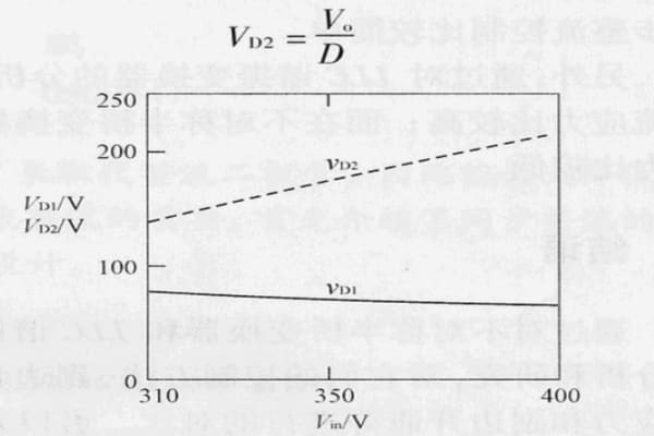
Figure 5: Voltage stress diagram of the secondary diode of a half-bridge flyback converter
Under the same conditions, the voltage stress on the secondary diode in the half-bridge resonant converter is much smaller than that in the half-bridge flyback converter, because the voltage stress on the secondary diode in the half-bridge resonant converter is twice the output voltage.
Therefore, a diode with a relatively low withstand voltage can be selected in the half-bridge resonant converter, thereby improving the efficiency of the circuit and reducing the material cost.
2.3 Comparison of the turn-on of the secondary diode
From the analysis of the half-bridge flyback converter, it can be seen that its secondary diode is hard-on, and the loss is relatively large; while from the analysis of the half-bridge resonant converter, it can be seen that its secondary diode is a zero-current switch, and the loss is relatively small, which can improve the efficiency of the converter. Therefore, in theory, the overall efficiency of the half-bridge flyback converter is slightly worse than that of the half-bridge resonant converter (but still far better than other converters).
2.4 Other aspects
First, in the half-bridge flyback converter, the duty cycles of the upper and lower switches are complementary, so the transformer in the half-bridge flyback converter has a DC bias phenomenon; while in the half-bridge resonant converter, the duty cycles of the upper and lower switches are equal, so the transformer in the half-bridge resonant converter does not have a DC bias phenomenon.
Secondly, the half-bridge resonant converter adjusts the output voltage by adjusting the operating frequency of the switch tube. Therefore, for the half-bridge resonant converter, it is more complicated to achieve synchronous rectification control; while the half-bridge flyback converter adjusts the output voltage by adjusting the duty cycle of the switch tube. Therefore, for the half-bridge flyback converter, it is relatively simple to achieve synchronous rectification control.
2.5 Current stress
Through the analysis of the half-bridge resonant converter, it can be seen that its current stress is relatively high and the output current ripple is relatively large; while in the half-bridge flyback converter, the current stress is relatively low and the output current ripple is relatively small.
2.6 Output voltage range
Through the analysis of the control principle of the half-bridge flyback converter, it can be seen that the output voltage range of the half-bridge flyback converter is wider, while the output voltage range of the half-bridge resonant converter is very narrow. Therefore, in the field of PD power supply with multiple output voltages, the half-bridge flyback converter is more suitable, and a DC/DC converter can be omitted.
3 Conclusion
Through the analysis and research of the half-bridge flyback converter and the half-bridge resonant converter, and the comparison of their control methods, secondary rectifier voltage stress and secondary opening, it can be known that the half-bridge resonant converter is more suitable for the development demand of power supply for high efficiency; while the half-bridge flyback converter is more suitable for the PD power supply field.